Studebaker SOLD............
Thanks, everyone!!!

Saturday, May 19, 2018

Thursday, March 15, 2018
Clean Stude
A couple of car buddies stopped by when we were doing a little paint cut n' buff for a very good (best friend).
The basic comment was, "If someone experienced comes and looks at the Stude they will take it home!! You've done all the hard work!"

Crawl under a 65 year old untouched car and then look at this one.
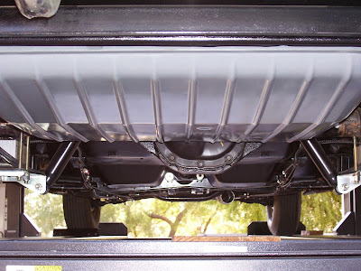
I actually discarded the old NASTY fuel tank in a dumpster 50 miles away. It stunk so bad, I could not even keep it in the back yard!
 Yes, it needs body and paint but you will not find many as nice as this to work on.

Not too shabby is it???
Thanks for looking.
The basic comment was, "If someone experienced comes and looks at the Stude they will take it home!! You've done all the hard work!"

Crawl under a 65 year old untouched car and then look at this one.

I actually discarded the old NASTY fuel tank in a dumpster 50 miles away. It stunk so bad, I could not even keep it in the back yard!


Not too shabby is it???
Thanks for looking.
Thursday, November 30, 2017
An Exhausting Project
I'm as old as dirt!
During the last 60 years, I've been known to do a little exhaust work. The small block Chevy always responded well to a low restriction exhaust system.
 With ceramic coated block huggers and a 2 1/2" to 3" Y pipe, this 350 will run OK.
I bent up the tube a couple of months ago before my old shop closed its doors and my access to the bender ended.
Click the Picture for a better view.
 Even though the Stude may end up looking and sounding a little "Land Speed", at Dirt Plus, 110 MPH with bugs on my teeth is my limit now!
I need a better 700R pan!
During the last 60 years, I've been known to do a little exhaust work. The small block Chevy always responded well to a low restriction exhaust system.

I bent up the tube a couple of months ago before my old shop closed its doors and my access to the bender ended.
Click the Picture for a better view.

I need a better 700R pan!
Saturday, July 29, 2017
53' Signal Lights
Please understand that virtually all the chromed pot metal on this jewel is pitted and corroded beyond use as is. Someone rechromed some of the trim without polishing out the pits, so now we have holes in the chrome and the trim is up against the wall in the back yard.
Since we had the internal grill pieces (1 '54 and 1 '53) we resurfaced and repaired both pieces and painted misty gold.
 At this point the plan was to install 12V amber bulbs for the Park/Turn 2 element receptacles. Unnoticed by me, the 1158 bulb is not interchangeable with the 1157A. It is a dual filament bulb but equal power and straight across pins.
NO PROBLEMO... the Dorman #85803 service receptacle will replace the original and allow the use of the 1157A bulb. Dim filament for parking and bright filament for turn signals.
Its not hard to replace the receptacle, but I recommend doing this prior to your refinishing job.

I needed a sharp putty knife, hammer, and Dad's old Blue Point tapered ream thats probably as old as I am.(old as dirt). Remove the old receptacle by bending the lip with the knife. A small amount of reaming (or filing) will allow the installation of the new unit with the retainer tabs bent straight.

The new unit must be seated completely or the bulb will not be able to be installed.
Click on the picture to view the retaining tabs bent over tightly after installation. Notice how close the bulb is!!
This is a mock-up of the grill assembly refinished in paint to match the body.
Just something to eyeball while the doors are being worked over.

If anyone ever asks you how many hours are involved in one of these old dogs, respond with TOO MANY!!!
Since we had the internal grill pieces (1 '54 and 1 '53) we resurfaced and repaired both pieces and painted misty gold.

NO PROBLEMO... the Dorman #85803 service receptacle will replace the original and allow the use of the 1157A bulb. Dim filament for parking and bright filament for turn signals.
Its not hard to replace the receptacle, but I recommend doing this prior to your refinishing job.

I needed a sharp putty knife, hammer, and Dad's old Blue Point tapered ream thats probably as old as I am.(old as dirt). Remove the old receptacle by bending the lip with the knife. A small amount of reaming (or filing) will allow the installation of the new unit with the retainer tabs bent straight.

The new unit must be seated completely or the bulb will not be able to be installed.
Click on the picture to view the retaining tabs bent over tightly after installation. Notice how close the bulb is!!
This is a mock-up of the grill assembly refinished in paint to match the body.
Just something to eyeball while the doors are being worked over.

If anyone ever asks you how many hours are involved in one of these old dogs, respond with TOO MANY!!!
Saturday, May 27, 2017
First Aspect
I'm going to eyeball this for a while. There is always the option of scuffing and repainting all misty....

The other option is to scuff
and paint it all misty but that would destroy the chrome that is left. No going back!!
I went fishing last week, it was absolutely wonderful.
I was the only boat on the lake and the only other fishermen were four eagles who astounded me with their expertise.


The other option is to scuff
and paint it all misty but that would destroy the chrome that is left. No going back!!
I went fishing last week, it was absolutely wonderful.
I was the only boat on the lake and the only other fishermen were four eagles who astounded me with their expertise.

Friday, March 31, 2017
Decisions
The decision here is what front and rear treatment to give the Stude. The Lowey coupe was years ahead of its time but later treatments are very attractive.
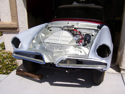
Even painting the rear of the grill shells, the chrome is driver quality at best.
As we move forward slowly, I am considering the solid color scheme of later unscrupulous modifiers.

This is one of the many options available on the 53/54 Stude. Its nice and clean reflecting current design techniques AND eliminates the $$$$ thousands in re-chroming bumpers and pot metal grills/trim pieces.
I'm into saving the $$$$ and spending it on GO FAST. Maybe we need to think about a supercharger! Instant go fast!!! I probably should have bought Milt's 500" Caddy engine. That was then, this is now!!
Thursday, February 9, 2017
Misty Gold
Yesterday was a very nice day, light breeze and 71 degrees at noon. It took about 3 1/2 hours to shoot the GM Gold Mist. I used 4 coats of Wandabase for coverage and then 2 coats of Southern Polyurethane's Universal clear.
For a trainee, the afternoon went better than expected. I really like the Wandabase HS, It lays down perfectly for me. Add the SPI clear and the job went very well.

I'm improving on little things, I cannot imagine painting a whole car at once!! I think this is pretty classy for the Stude!

For a trainee, the afternoon went better than expected. I really like the Wandabase HS, It lays down perfectly for me. Add the SPI clear and the job went very well.

I'm improving on little things, I cannot imagine painting a whole car at once!! I think this is pretty classy for the Stude!

Saturday, February 4, 2017
Shall We Continue??
"Run Hard and Put Away Wet"
That was last year, it's taking a little longer than expected but we're moving forward. Although not sure of the future of my land speed retro rod, I'm going ahead with the 63 Hawk dash.
 I've begun the finishing of the walnut after fitting the components to the dash.
The dash had a preliminary sanding of the epoxy primer yesterday, and will get two coats of building primer today.
I hope to have a finish painted unit to display next week.
Friday, July 29, 2016
Delays
Due to a couple physician induced issues, The Stude is being placed on the back burner for a while. My buddies are going to assist me in moving it to an unused garage so they have access to the shop.

The plan is to be back on this in November.
Use great care and all available resources when selecting a physician and/or treatment program!
I'm pleased with the prepared engine compartment. Not to bad for a hobby car!!

The plan is to be back on this in November.
Use great care and all available resources when selecting a physician and/or treatment program!
I'm pleased with the prepared engine compartment. Not to bad for a hobby car!!
Thursday, May 12, 2016
Paint
It was finally time to paint the inner fenders. This gets them back on the car and out of my way. It's unbelievable how many pieces are involved in reworking a vehicle.
 You beat ,sand, fill, prime, sand until it has to end.... then you paint!
This will be the color of the car (Chevrolet Gold Mist) in basecoat/clearcoat.
The fenders are epoxy primed inside and out with SPI for the main body finish program.
 When you add a 63 year old fan shroud to the project, you can believe me that a few more days work are involved.
I'm pleased with the results, the SPI clear sprays very nicely. I wish I had the ability/facilities to shoot the whole car.
Why does every owner of one of these derelicts need to drill a few new holes in the car???

This will be the color of the car (Chevrolet Gold Mist) in basecoat/clearcoat.
The fenders are epoxy primed inside and out with SPI for the main body finish program.

I'm pleased with the results, the SPI clear sprays very nicely. I wish I had the ability/facilities to shoot the whole car.
Why does every owner of one of these derelicts need to drill a few new holes in the car???
Wednesday, April 6, 2016
Holy Moly!!!!
My buddies seemed to think the body on the Stude was pretty nice. I wanted the inner fenders cleaned better than I was able to and the rest cleaned would be nice. There appeared to be earlier repair that should be addressed.
Nice clean fenders??? Media blast.
 How about clean fenders, no nice adjective. The sin exposed cause a bit of depression and anxiety.
Ever seen the TV shows where they skim coat the car and then 18 guys block sand it for 20 hours (360 man hours) overnight and its ready to paint the next day???
I think these fenders were prepped by the same guys in East L.A. in 1989!!!
I have been beating the dents out and welding the holes for the past 2 weeks and am getting close to an epoxy seal coat of primer.
When I need a little stress relief, I warm up the Model A and go for a ride.

When you put the pedal
down hard, the street rod hobby is instantly all rose
tinted!!!!!! and the fenders are only a memory!
Nice clean fenders??? Media blast.

Ever seen the TV shows where they skim coat the car and then 18 guys block sand it for 20 hours (360 man hours) overnight and its ready to paint the next day???
I think these fenders were prepped by the same guys in East L.A. in 1989!!!
I have been beating the dents out and welding the holes for the past 2 weeks and am getting close to an epoxy seal coat of primer.
When I need a little stress relief, I warm up the Model A and go for a ride.

When you put the pedal
down hard, the street rod hobby is instantly all rose
tinted!!!!!! and the fenders are only a memory!
Saturday, February 20, 2016
Engine Compartment
I have been tinkering with the components of the engine compartment. I want to use the Stude shroud and throttle linkage as well as a flex fan. In Vegas, max cooling is absolutely necessary.
I do exhaust, so attempting to use manifolds in this instance is of no interest to me. The block huggers are so clean and easy to access, no decision to make.

I am using the original steering components. The center bell crank is tight under the shroud in the original position.
To lower the shroud and engine would require cutting a major portion of the shroud away.
Look at this long and hard prior to the cut. This large shroud needs all of its integrity to maintain its shape.
The short water pump is the only option when using the shroud and it appears that a 17" fan is going to be the answer to the blade.
Friday, February 19, 2016
The Split
Only those of us old enough (old as dirt), have experienced the terror of slamming on the brakes of dad's 1954 Starlight on the San Bernadino Freeway and having the pedal go clear to the floor several times, You pull the emergency through the firewall, move to the right and lightly kiss the concrete wall and then take the Atlantic off ramp (15 mph) at 45 mph and bury the car in the curb after you blew the stop sign. Absolute gospel!! Ever heard of freewheeling in O.D........
 Even though we are going to set this up with drum brakes, I will have a split system for safety.
The Turner Brake kit is well thought out and is precision enough to be tough to install. It all fits perfectly in the 63 year old Stude!!
I needed four adapter brake fittings and the fools at the parts stores cannot function even if you dare tell them that they are for a 53' Commander?????
For the 8.8 Ford (7/16-27) you will need 2 ea. Dorman 072550BP to attach the 3/16" brake lines (3/8-24). The original Ford lines are 3/16 and use special 7/16-27 nuts so if you still have them, you can used the fittings and reflare your new lines.
Do not use Edelman fittings in either of these applications (JUNK).
The adapter fittings for the Master Cylinder are ONLY AGS BLF-20C.
They fit!!!
Brakin' Boss
I wish!! No breaks in site on this job!!
The Ford rear axle arrived with missing and damaged components. I needed all new everything except the backing plates. I have never understood why junkyard dogs cannot remove components instead of cutting them off.
 As I was looking at the empty 8.8 Ford backing plates, I realized that emergency brake cables are first. Trotting back and looking at the old Stude 44.............
wouldn't it be nice if the brake cable from the 44 could be used with all of the rest of the Stude hardware in the 8.8 and on the Coupe.
NO PROBLEMO !!!!! If you shorten the inner cable coil to 4 1/2" , ream the backing plate holes a wee bit, and then shorten the intermediate cable coil spring 2", it works. I mean it works as it did in 1953!!!
I won one, I won one!!! I'm going to take myself out to lunch.
The Ford rear axle arrived with missing and damaged components. I needed all new everything except the backing plates. I have never understood why junkyard dogs cannot remove components instead of cutting them off.

wouldn't it be nice if the brake cable from the 44 could be used with all of the rest of the Stude hardware in the 8.8 and on the Coupe.
NO PROBLEMO !!!!! If you shorten the inner cable coil to 4 1/2" , ream the backing plate holes a wee bit, and then shorten the intermediate cable coil spring 2", it works. I mean it works as it did in 1953!!!
I won one, I won one!!! I'm going to take myself out to lunch.
Dashing
We have spent some time arranging and mocking up the later fiberglass dash. It fits perfectly in the 53', even being 10 years younger.
 This is the mocked up unit as needed for the steering column measurement.
The Hawk dash is definitely more attractive and versatile than the 53' unit.

The Hawk dash is definitely more attractive and versatile than the 53' unit.
Undercar..........
I had a nice 2 piece driveshaft (no wear) and decided to try to use it. With the Ford 8.8 rear axle, length is the issue. The original shaft uses the 1310 series u-joint, and Spicer makes a 1310 flange yoke for the 8.8 pinion flange. Use


2-2-1379 for a direct bolt-on yoke.

While replacing the original carrier bearing, I moved it about .090" to the rear and shimmed the rubber mount back about 3/16" and achieved full insertion of the splined shaft.
The front section uses a GM slip yoke, 1310 joint and is shortened as required.
I want to repeat the necessity for insert spacing the frame when cross bolting.

I fabricated these two spacers from 7/16 i.d. X 9/16 o.d tube and 1/2" washers.
I drilled the nut side of the frame 7/16" and the washer/bolt side 916".
Tightened, the 14 gauge Stude frame will not collapse.
Friday, November 20, 2015
700R4 Crossmember
I purchased an early chevy truck crossmember kit for the stude. I wanted a unit with a 2" drop simply for exhaust pipe clearance. I don't like dealing with powder coated components when fabricating but the price was right, and I can grind off the PC.
A lot to consider in this step, measure, measure and measure again. Then cut!

Te first step was to locate the output shaft in the center of the original x-member. The original center passage is centered between the frame rails regardless of Studebaker's right and left offsets.
Measure AND optically locate the trans.
Notice that I am holding the rear of the engine/trans with a heavy ratchet strap. We know that the Stude frame is flexible, are we distorting it with the strap?? Yes we are! I placed a stand under the trans and removed the load from the strap and the frame expanded 3/8" (wow). The original stude transmission cross member would have prevented this, but it will not fit without modification (later step).
Measure, measure, make no assumptions with my Studebaker.

I cleaned and modified the mounts in the kit (nice radius that matches the frame rail) and re-drilled for me. Mocked up with two bolts through the frame flange and one through the frame with a supporting tube. The front bolt actually replaced one rivet in the body mount support plate. This mount is offset to the rear matching the new xmember.

I may be loosing it but I always try to template before cutting (thanks, Dad). This is a top view template of the xmember. It proved its value as it pointed out cut angles and 1/4" offset in the mount location that I did not see.
Measure, measure, trim template, and then throw the sacred chicken bones on the floor and CUT IT!!

One extra trim for angle, and tacked in place.
This xmember setup is nice since it sits in a tapered portion of the frame and simply slides out to the rear for future service.

We be done!
I have 1/2" of spacers between the trans mount and the crossmember at this time. The trans can move up and down as the drive shaft and carburetor orientations require as we move along.
The rear axle assembly is absolutely centered on the leaf springs. The pinion is of course offset to the passenger side. Studetest # 17 is the fact that the wheels are not equidistant from the fenders or the frame??? No answer to this one. Today I am going to shift the axle assembly 1/2" to the driver side.
I have no other answer to this. The original axle is also centered so I guess the offset was factory??
I will check the wheels first to be sure they are identical, and then move the mounts. The spring mounts are not welded to the housing yet pending drive line angle requirements.
Saturday, November 14, 2015
The Good, The Bad, and The Wonderful
After 55 years of fooling with these junks, I just spent the best $40 on a tool in a long, longlong time!

No more manhandling a 652 lb. engine and trans assembly with chain locations and strong arm tactics. If you don't have one of the levelers, get one....they are the wonderful!
The good were the spacers. I will not have to lower the shroud as they specified nor did I have to cut the mounting pads to clear the engine mounts.
On initial installation loading, I have 7/8" !!!!!! clearance between the 8" harmonic balancer and the steering bellcrank with only 3/4" of machined polyethylene spacer. It will probably be slightly less when tightened and settled.
 Click to enlarge any photo.
The leveler tilts and levels the load as necessary, I never touched the firewall.
At the point above, I learned that the blank fuel pump mount casting hit the original mount pad......here come the sawsall!!

About five minutes later, 1/2' of the pad was on the floor with my sacred chicken bones. I will box in and weld the gap when its up in the air. No stopping now!
The motor is level and straight and the 700R pan seems to be level with the bottom of the frame when the output shaft is aligned nicely with the center crossmember. I'm just mocked up at this point and a transmission support xmember will be next. There seems to be plenty of room for lines and linkage as well as ample floor clearance.
I must admit that the specified mount location was correct and I was wrong. I ended up using the front hole set instead of the rear as I expected. Moving the mounting hole forward did allow for the 1 3/4" lower section of the early ford mount under the mounting pad.

Things are looking good but what if I didn't have a spacer prepped ahead of time, about a 4 hour delay.

No more manhandling a 652 lb. engine and trans assembly with chain locations and strong arm tactics. If you don't have one of the levelers, get one....they are the wonderful!
The good were the spacers. I will not have to lower the shroud as they specified nor did I have to cut the mounting pads to clear the engine mounts.
On initial installation loading, I have 7/8" !!!!!! clearance between the 8" harmonic balancer and the steering bellcrank with only 3/4" of machined polyethylene spacer. It will probably be slightly less when tightened and settled.

The leveler tilts and levels the load as necessary, I never touched the firewall.
At the point above, I learned that the blank fuel pump mount casting hit the original mount pad......here come the sawsall!!

About five minutes later, 1/2' of the pad was on the floor with my sacred chicken bones. I will box in and weld the gap when its up in the air. No stopping now!
The motor is level and straight and the 700R pan seems to be level with the bottom of the frame when the output shaft is aligned nicely with the center crossmember. I'm just mocked up at this point and a transmission support xmember will be next. There seems to be plenty of room for lines and linkage as well as ample floor clearance.
I must admit that the specified mount location was correct and I was wrong. I ended up using the front hole set instead of the rear as I expected. Moving the mounting hole forward did allow for the 1 3/4" lower section of the early ford mount under the mounting pad.

Things are looking good but what if I didn't have a spacer prepped ahead of time, about a 4 hour delay.
Friday, November 13, 2015
SBC Engine Mounts
The Studebaker/SBC engine mounts that we purchase are not Studebaker specific. These are actually universal mounts to off set the Chevy engine 2" or 3 1/4" rearward in stock or roundy-round cars (racing). Will they work??? yes.
One might find the instructions a little vague at best.
 These are 9/16" slots for 1/2" bolts. The rear holes are a 2" setback and the fronts are for 3 1/4" set back.
Using the original Stude mount (1" tall, 3/8" stems) leaves a lot of slop in the assembly.
I have experience in ripping the older style mounts in half under heavy load so original mounts are not used here.
 The early Ford style mount is the same height and thru bolt mounted for a much stronger cushion assembly. These are sold as sets for a very reasonable price. They ship these with the wrong size and style of bolts. Discard the 7/16" and use 1/2" as they were designed for. A 1 3/16" hole is required for the correct interlocking installation.
The engine mounts that I purchased require a minimum 19 1/2" width between the center of the mounting holes. Center your layout in the chassis. No right/left offset.
Click on pictures for full view
 Options??
The black rear location is as provided in the instructions (kinda). The red hole location is what I think I need. The yellow location is the 3 1/4" setback hole (front).
My location should give me 1" clearance behind the GM HEI distributor and is 1 3/8" forward of the recommended mounting. It is also the recommended engine location if I used the front pair of holes. Clear as mud right?? If I mount in the 2" offset holes, the engine is forward of their recommendation but if I used the 3 1/4" holes, the engine is actually where they recommended.
 The white dots are 19 1/2" apart and where I want them to be to have distributor clearance. Measure 10 times and drill once. I also throw sacred bones on the floor and read them for confirmation.
Remember that the stude firewall distributor cavity is offset to the driver side and the chevy distributor is offset to the passenger side.
I was fortunate to inspect a '54 coupe with a chevy installed as my instructions specified. All was peachy except the harmonic balancer appeared to be 1/4" above the steering bellcrank. I want more clearance than that.
Kicking this around, I want more clearance on the bellcrank, If I space the mounts up 1", I won't need to lower the radiator shroud, and I will not have to trim and box the frame mounting pads since they then clear the engine mounts? This is the way I am going to go.
 I am actually going up 7/8" with this 3/4' high density polyethylene spacer that is milled to the contour of the pad and counter bored to interlock with the lower insulator half and the upper metal cup plus one 1/8" stainless washer. The pad is interlocked but I added a 1/4-20 flathead machine screw as an additional locator.
All of this is "the plan" I will know soon if it all "comes together".

This is the mount assembly interlocked in place. It looks tall but is actually only 3/4" taller than the original stude mount.

Now as ready as can be with the "plan".
The '93 chevy 350/700r4 is ready for a test fit. I'll let you know if the "plan" is valid.

One might find the instructions a little vague at best.

Using the original Stude mount (1" tall, 3/8" stems) leaves a lot of slop in the assembly.
I have experience in ripping the older style mounts in half under heavy load so original mounts are not used here.

The engine mounts that I purchased require a minimum 19 1/2" width between the center of the mounting holes. Center your layout in the chassis. No right/left offset.
Click on pictures for full view

The black rear location is as provided in the instructions (kinda). The red hole location is what I think I need. The yellow location is the 3 1/4" setback hole (front).
My location should give me 1" clearance behind the GM HEI distributor and is 1 3/8" forward of the recommended mounting. It is also the recommended engine location if I used the front pair of holes. Clear as mud right?? If I mount in the 2" offset holes, the engine is forward of their recommendation but if I used the 3 1/4" holes, the engine is actually where they recommended.

Remember that the stude firewall distributor cavity is offset to the driver side and the chevy distributor is offset to the passenger side.
I was fortunate to inspect a '54 coupe with a chevy installed as my instructions specified. All was peachy except the harmonic balancer appeared to be 1/4" above the steering bellcrank. I want more clearance than that.
Kicking this around, I want more clearance on the bellcrank, If I space the mounts up 1", I won't need to lower the radiator shroud, and I will not have to trim and box the frame mounting pads since they then clear the engine mounts? This is the way I am going to go.

All of this is "the plan" I will know soon if it all "comes together".

This is the mount assembly interlocked in place. It looks tall but is actually only 3/4" taller than the original stude mount.

Now as ready as can be with the "plan".
The '93 chevy 350/700r4 is ready for a test fit. I'll let you know if the "plan" is valid.

Friday, October 23, 2015
53' to 63' Dash
The 53' dashboard was somewhat tweaked (I hope his knee healed well) and frankly, I could not visualize modifications and repair that would result in a dash that I liked.
There was a Studebaker meet here in Henderson and I went shopping. Not much there for me, but I did score a 63' fiberglass dash complete with the steel crossbar and brackets.

The amazing part of this is that it bolts into the '53 Starlight perfectly. No changes in the cowl in 10 years.
With the dash pad (rag) removed, I have been cleaning and blocking the unit with 80 grit. There are a few imperfections and way to many holes, but this is going to be cool!
My instruments don't fit and I don't do radios so the concept is to overlay the dash with black walnut.

I found a supplier in Vegas and picked up a nice plank to fab the overlay.
Everything is a project but this is not a bid job and I do have the time. The 34' Chevy is peeking out the garage door.
I really don't do much wood but with a piece as nice as this I think I can succeed. There is enough here to do this job twice.
Click on the pictures for a larger view.
 This is a nicely figured piece!!
I hope to have an engine mount presentation in the next couple weeks to answer the questions I had before starting this project.
There was a Studebaker meet here in Henderson and I went shopping. Not much there for me, but I did score a 63' fiberglass dash complete with the steel crossbar and brackets.

The amazing part of this is that it bolts into the '53 Starlight perfectly. No changes in the cowl in 10 years.
With the dash pad (rag) removed, I have been cleaning and blocking the unit with 80 grit. There are a few imperfections and way to many holes, but this is going to be cool!
My instruments don't fit and I don't do radios so the concept is to overlay the dash with black walnut.

I found a supplier in Vegas and picked up a nice plank to fab the overlay.
Everything is a project but this is not a bid job and I do have the time. The 34' Chevy is peeking out the garage door.
I really don't do much wood but with a piece as nice as this I think I can succeed. There is enough here to do this job twice.
Click on the pictures for a larger view.

I hope to have an engine mount presentation in the next couple weeks to answer the questions I had before starting this project.
Subscribe to:
Posts (Atom)